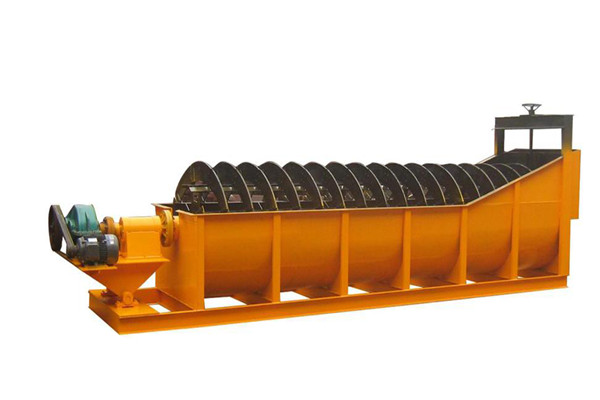
Spiral classifier
This classfiers suitable for dewatering,medium,drainaging amd spraying in ore clressing for medium and fine naterial wet and dry classifying in mine.
Such machine is mainly used in the production flow of metal processing. According to the difference in sedimentation rate of mineral particles and mud, the particle sizes of ores with 14-325 meshes are classified. Waste mud or water for ore sand can be separated from the ores.
Such machines are divided into single spiral classifiers and double spiral classifiers. Beside, they are also divided into high weir spiral classifiers and submerged spiral classifiers. If the overflow edge is higher than the center line of spiral shaft and lower than the external diameter of spiral at the overflow end, the spiral classifiers are high weir ones. If the overflow edge is higher than the center line of spiral shaft and also higher than the external diameter of spiral at the overflow end, the spiral classifiers are submerged ones. High weir classifiers are usually used for the classification with particle size of below 100 meshes. Submerged classifiers are usually used for the classification with particle size of below 200 meshes.
3.Technology parameters
|
Model |
Spiral Dia. |
Spiral Speed |
Output |
Motor Power |
Weight |
|
Circulating Load |
Overflow Quantity |
Lift Lower |
Drive |
|
mm |
r/min |
t/24h |
t/24h |
kw |
kw |
t |
|
High-weir single spiral classifier |
|
FG-3 |
”Ą300 |
8.3-2.2 |
30-80 |
10-30 |
2.2 |
1.1 |
0.67 |
|
FG-5 |
”Ą500 |
8.5-15.5 |
143-261 |
32 |
2.2 |
1.1 |
1.6 |
|
FG-7 |
”Ą750 |
4.5-9.9 |
256-564 |
65 |
2.2 |
3 |
2.83 |
|
FG-10 |
”Ą1000 |
3.5-7.6 |
473-1026 |
85 |
2.2 |
5.5 |
4 |
|
FG-12 |
”Ą1200 |
5Īó6Īó7 |
1170-1600 |
155 |
2.2 |
5.5 |
8.54 |
|
FG-15 |
”Ą1500 |
2.5Īó4Īó6 |
1140-2740 |
235 |
2.2 |
7.5 |
11.68 |
|
FG-20 |
”Ą2000 |
3.6Īó5.5 |
3890-5940 |
400 |
3 |
11Īó15 |
20.45 |
|
FG-24 |
”Ą2400 |
3.64 |
6800 |
580 |
3 |
15 |
25.65 |
|
FG-30 |
”Ą3000 |
3.2 |
11650 |
893 |
4 |
22 |
40.9 |
|
High-weir double spirals classifier |
|
|
2FG-12 |
”Ą1200 |
5Īó6Īó7 |
2340-3200 |
310 |
2.2Ī┴2 |
5.5Ī┴2 |
15.84 |
|
2FG-15 |
”Ą1500 |
2.5Īó4Īó6 |
2280-5480 |
470 |
2.2Ī┴2 |
7.5Ī┴2 |
21.11 |
|
2FG-20 |
”Ą2000 |
3.6Īó5.45 |
7780-11880 |
800 |
3Ī┴2 |
22Īó30 |
36.34 |
|
2FG-24 |
”Ą2400 |
3.67 |
13600 |
1160 |
3Ī┴2 |
30 |
53.49 |
|
2FG-30 |
”Ą3000 |
3.2 |
23300 |
1785 |
4Ī┴2 |
40 |
73.03 |
|
Submerged single spiral classifier |
|
|
FC-12 |
”Ą1200 |
2.5Īó4Īó6 |
1170-1630 |
120 |
2.2 |
7.5 |
11.1 |
|
FC-15 |
”Ą1500 |
2.5Īó4Īó6 |
1140-2740 |
185 |
2.2 |
7.5 |
15.32 |
|
FC-20 |
”Ą2000 |
3.6Īó5.5 |
3890-5940 |
320 |
3 |
11Īó15 |
29.056 |
|
FC-24 |
”Ą2400 |
3.64 |
6800 |
455 |
4 |
18.5 |
37.267 |
|
FC-30 |
”Ą3000 |
3.2 |
11650 |
705 |
4 |
22 |
46.2 |
|
Submerged double spiral classifier |
|
|
2FC-12 |
”Ą1200 |
3.8Īó6 |
1770-2800 |
240 |
2.2Ī┴2 |
7.5Ī┴2 |
19.61 |
|
2FC-15 |
”Ą1500 |
2.5Īó4Īó6 |
2280-5480 |
370 |
2.2Ī┴2 |
7.5Ī┴2 |
27.45 |
|
2FC-20 |
”Ą2000 |
3.6Īó5.5 |
7780-11880 |
640 |
3Ī┴2 |
22;30 |
50 |
|
2FC-24 |
”Ą2400 |
3.67 |
13700 |
910 |
3Ī┴2 |
30 |
53.491 |
|
2FC-24 |
”Ą2400 |
3.67 |
13700 |
910 |
4Ī┴2 |
37 |
65.283 |
|
2FC-30 |
”Ą3000 |
3.2 |
23300 |
1410 |
4Ī┴2 |
45 |
84.87 |
Note: (1) In the table, C represents submerged type, G represents high weir type, 2F represents double spiral type, and F represents single spiral type. (2) The production capacity in the table is figured out based on empirical formula according to factors such as overflow particle size, revolution speed of screw and screw diameter in ore ratio.
IV. Structure Description
1. General Description
This kind of machine is composed of transmission mechanism, (left, right) spiral water tank, lifting device, lower support, lubricating device, ore discharge valve, feed inlet, etc (See the attached general drawing for details).
The water tank of this machine is installed obliquely. The angle of inclination is determined according to equipment configuration of equipment in the process flow. The (left, right) spirals driven by the transmission mechanism rotates in the water tank. The finely grained slurry enters the water bank from the feed inlet at one side and forms one slurry precipitation zone, whose surface area and volume depends on the value of the water tankĪ»s inclination angle and the height of overflow edge. The spirals rotating at a low speed play a certain stirring role. After the slurry is stirred, the light and fine particles float above the surface and overflow from the overflow edge. Then they flow into the next working procedure of ore dressing. The heavy and thick particles sink into the bottom of the water tank and become return sand which is transported by the spirals to the ore discharge mouth for discharge.
If ore grinding and classification are closed loop operation, the return sand discharged from the ore discharge mouth still goes into the mill for further grinding. Classifiers normally form closed loop operation together with mill.
Function Diagram
1. Transmission mechanism 2. Left spiral 3. Right spiral 4. Lower support
5. Lifting Device 6. Water tank
4. Structure Description of Main Parts
(1) Transmission mechanism: ¦Č3000, ¦Č2400 and¦Č2000 classifiers consist of motor, coupling, speed reducer coupling cylinder and bevel gear pair while¦Č1500 and¦Č1200 classifiers consist of motor, V-belt, and speed reducer cylinder gear pair. The transmission mechanism drives the rotation of spiral.
(2) (Left, right) spirals: Spirals consist of hollow shaft, bracket, spiral vane, iron liner, etc. The upper ends are supported in the cross-shaft sleeves while the lower ends are supported in the lower support. Hollow shafts whose diameter is over 500mm are welded with two semicircular long steel plates so that shaft fracture due to poor welding quality caused by transverse weld can be avoided. For hollow shafts with small diameters (such as 325mm), seamless steel pipes are used. When the spirals are rotating, the spiral vanes stir the slurry slightly. The light and fine particles are discharged from the overflow weir while the heavy and thick particles are conveyed to the ore discharge mount for discharge. Anti-wear life of iron liner is very important. It needs further study.
(3) Lower support: As lower support long operates submerged in the slurry, its sealing is very important. The sealing of lower support directly affect the service life of bearings. In design, it is of the multilayer cotton yarn valve-clack type packing and high-pressure grease double seal structure, and is equipped with manual dry pumps on the lubricating device. It can fill grease to the inside of bearings on a regular basis to maintain its sealing property.
(4) Water tank: Water tank is welded through steel poles and all kinds of profile steel. Due to difficulty in transportation, the water tanks of¦Č3000, ¦Č2400 and¦Č2000 classifiers are generally assembled and welded at the workplace. The water tank shall bear the weight of the machine itself and all load. Therefore, the design of foundation supporting the water tank is very important (the structure should be reasonable and the foundation shall be firm). To avoid the water tank becomes deformed due to improper supporting and thus affect the operation of machine, the diagram of foundation structure is attached for this machine which can serve as the reference basis for foundation design.
(5) Lubricating device: To improve the lubricating conditions of machines and better the lubricating and sealing property of lower support bearings, the lubrication method of manual centralization lubrication is adopted for¦Č3000, ¦Č2400 and¦Č2000 classifiers. It is equipped with manual dry pumps and operating valve and can infuse grease to the insides of all bearings on a regular basis. Some users can decide if the lubricating control console is installed along the left wall or right wall according to specific operating conditions. Or it can be installed otherwise. The lubrication method of manual lubrication is adopted for¦Č1200 and¦Č1500 classifiers.
(6) Drain valve: Drain valve is installed at the lower of the water tank so that slurry can be discharged from the water tank when necessary. During normal operation, the valve can be shut off.
(7) Lifting device: The lifting device consist of motor, wheel reducer, bevel gear pair, nut with thread, and other parts. When the classifier stops working, lifting device is installed with an aim to preventing the solid in the slurry from precipitating and pressing the spirals so as to damage machine parts as well as facilitating repair work. When the classifier stops working, the spirals must be lifted from the water tank to get most of the spirals away from the slurry. For the safety of lifting operation, stroke end switch is installed so that the lifting journey can be controlled automatically. See Figure 2 for Electrical Schematic Diagram.
Besides, electrical schematic diagrams for spiral classifier rotation and lifting linkage control are designed (Figure 6). When the classifier stops working, with the startup of lifting device the spirals can automatically be lifted to a certain height. When the classifier is working, the spirals can be automatically lowered to the working position during the rotation of lifting device to keep the hollow from being fractured due to overload. Whether to install linkage control electric device shall be determined by the user according to actual conditions. The manufacturer does not provide parts and components required by this electric installation.
Figure 2: Electrical Schematic Diagram of Lifting Journey Control of Lifting Device
RD ©C Fuse TA ©C Stop light
SC ©C Contactor for lifting SXK ©C Lifting journey switch
JC ©C Contactor for lowering JXL ©C Lowering journey switch
JA ©C Lowering startup
|